| Product |
| BPU204A-1 |
Price: HK$174.00 |
| |
| |
(1) Brand
(2) Data Transfer
(3)Dimensions
(4) USB connection
(5) Work with
(6) DLL for LCD Smartie
(7) DLL for programming
(8) Software
(9) Driver
|
: Lcdmod Kit
: USB 1.1 compliant
: 38x38x5.5mm
: mini-B
: Lcd Smartie, lcd4linux and LCDProc
: Free(Work with Win 98 / XP, Vista, Windows 7 32&64 bit)
: Free(Work with Win 98 / XP, Vista, Windows 7 32&64 bit)
: Free Lcd Smartie (Work with Win 98 / XP, Vista, Windows 7 32&64 bit)
: Free (Work with Win 98 / XP, Vista, Windows 7 32&64 bit)
|
|
Ship by registered airmail with tracking number.
User Manual : U204GMB-B1.pdf
Windows Driver : LCD2USBInf.zip
Programming DLL : LCD2USB-smartie.zip
Download "LCD Smarite" here
|

|
|
Soldering Guide
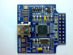 |
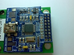
| 1. Here is the BPU204A-1 module |
|
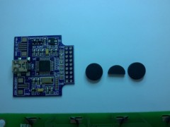 |
| 2. Use rubber pad RP10x3-1 in Accessories as liner |
|
 |
| 3. Place those liner with double side tape at suitable positons |
|
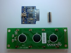 |
| 4. Use pin header (both sode 3mm long) PIN2x8-2 in Accessories for connecting between LCD module and BPU204A-1 |
|
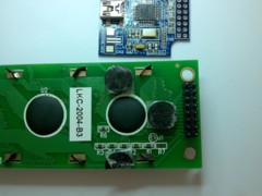 |
| 5. Place the pin header at the right position |
|
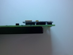 |
| 6.Ths side view of assembly |
|
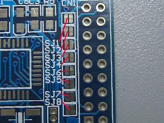 |
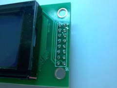
| 7. Solder jumpers |
|
 |
8. Photo show solder short jumper for our LKC-2004-B3/C3. Please take a look LKC-2004-B3/C3 's pin out in specification. Use hole 3 to hole 18 of CN1 for single controller LCD connection. SJ1 to SJ4 are for backlight polarity, SJ5 to SJ8 are for power polarity.
For single controller LCD pin 15 = LED + and pin 16 = LED - ->(SJ1 short, SJ2 open, SJ3 short, SJ4 open). For LCD pin 15 = LED - and pin 16 = LED + -> (SJ1 open, SJ2 short, SJ3 open, SJ4 short).
For single controller LCD pin 1 = VSS and pin 2 = VDD/VCC -> (SJ6 open, SJ5 short, SJ7 short, SJ8 open). For LCD pin 1 = VDD/VCC and pin 2 = VSS -> (SJ6 short, SJ5 open, SJ7 open, SJ8 short). |
|
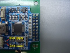 |
9. Photo show solder short jumper for our LKC-4004-A2. Please take a look LKC-4004-A2 's pin out in specification. Use hole 1 to hole 16 of CN1 for dual controller LCD connection. SJ1 to SJ4 are for backlight polarity, SJ5 to SJ8 are for power polarity.
For dual controller CN3 Upper = LED + and CN3 Lower = LED - ->(SJ1 short, SJ2 open, SJ3 short, SJ4 open). For CN3 Upper = LED - and CN3 Lower = LED + -> (SJ1 open, SJ2 short, SJ3 open, SJ4 short).
For dual controller LCD pin 13 = VSS and pin 14 = VDD/VCC ->(SJ6 short, SJ5 open, SJ7 open, SJ8 short). For LCD pin 13 = VDD/VCC and pin 14 = VSS ->(SJ6 open, SJ5 short, SJ7 short, SJ8 open). |
|
 |
| 10. Here is the completed module ready to test |
|
|
|
|
 © 2001-2099 Lcdmod Kit. All Rights Reserved.
http://www.lcdmodkit.com
|
|

)
)
)
)
)
)
)
)
)
)
)